
Dude’s Cab Manual
PDF version HERE.
The Dude’s Cab is a card that allows you to take full advantage of a Virtual Pinball Machine.
It has 32 button inputs, an accelerometer, an input for a ball shooter, an expansion card system that allows you to control up to 128 classic toys via the DOF, and sockets are provided for future functions and an expansion card (MX DONNY) that allows you to control addressable LEDs.
Each output has continuous limiting functions available (to reduce the maximum output voltage), CHIME LOGIC functions (output shutdown after x milliseconds), FLIPPER LOGIC (output voltage reduction after x milliseconds), and NIGHT MODE (to disable sound toys using a button).
The plunger (if you use it) has a function that allows you to easily emulate a Launch Ball button and/or a FIRE button by either pushing the plunger all the way down or pulling it all the way up (or both), and is easily configurable.
The accelerometer has a virtual TILT button that will activate this function when the accelerometer moves outside its limit zone (which you can of course configure as you wish).
It works with computers, game consoles, Android systems, and connects via a USB-C port.
The board is powered by this USB-C connector and requires no other power supply.
It is controlled by an oversized dual-core microcontroller, one handling inputs and the other handling outputs, for maximum efficiency and reduced latency.
You can connect your various buttons, plungers, or expansion boards using screw terminals or ribbon cables to simplify your wiring.
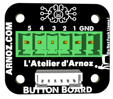
To simplify your wiring even further, you can use Button Boards, which are small cards that connect via a ribbon cable to the Dude’s Cab and allow you to have a screw terminal as close as possible to your buttons.
The ribbon cable connectors are JST-PH 6-pin.
A – WIRING
1-WIRING OF BUTTONS
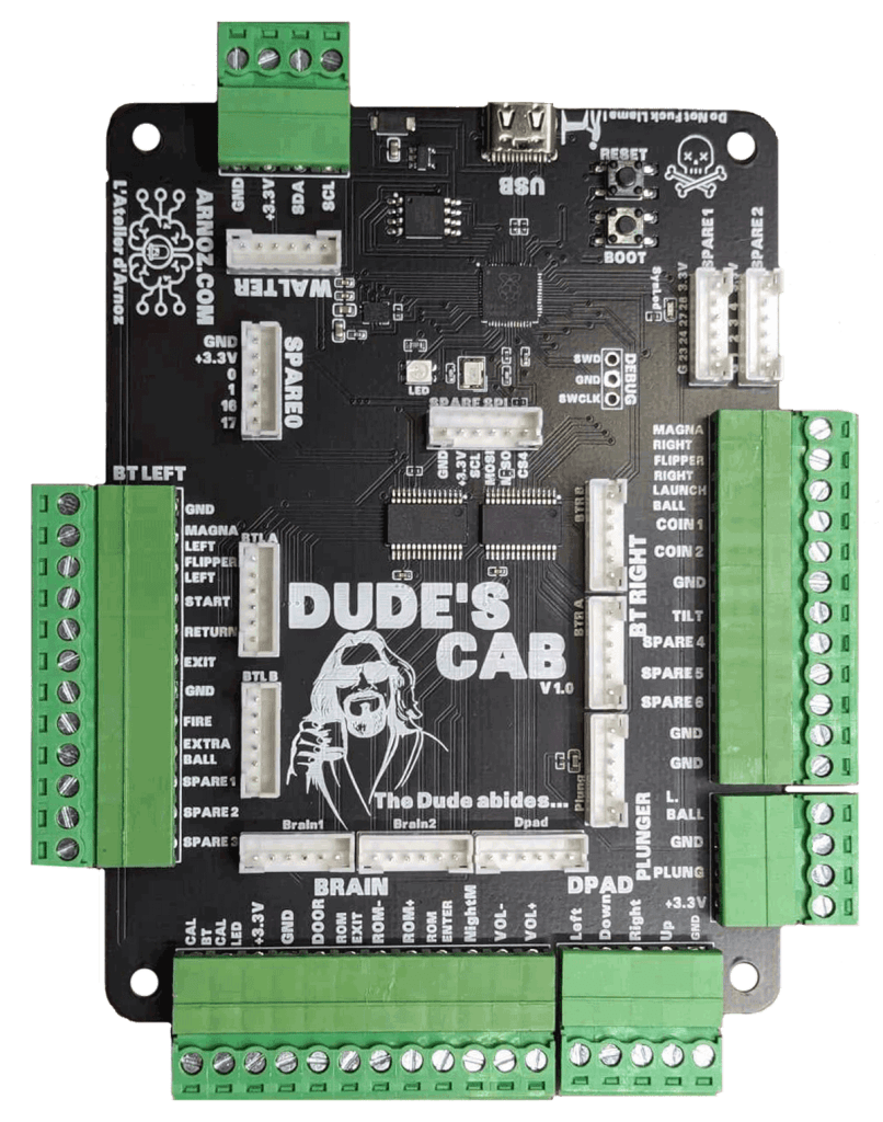
All GND sockets are connected to the same potential, so it doesn’t matter which one you use.
There are 7 GND sockets on the board for easy access to simplify wiring.
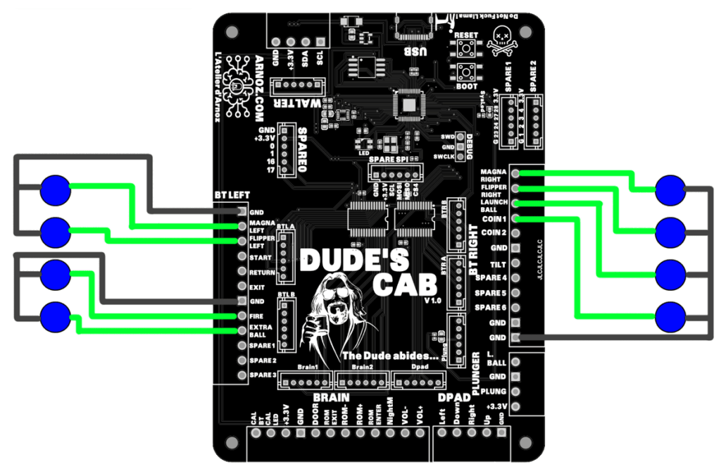
Each button must be connected on one side to the GND of the socket and on the other side to the input corresponding to the function of your button.
The screen prints and default functions on the board are only there to simplify configuration; you can easily modify the function and characteristics of all the sockets via the configurator.
You have the standard button inputs, plus 4 inputs for navigating the menus (DPAD), 6 spare sockets allowing you to add the functions you want, and a Calib input for easily calibrating the Plunger.
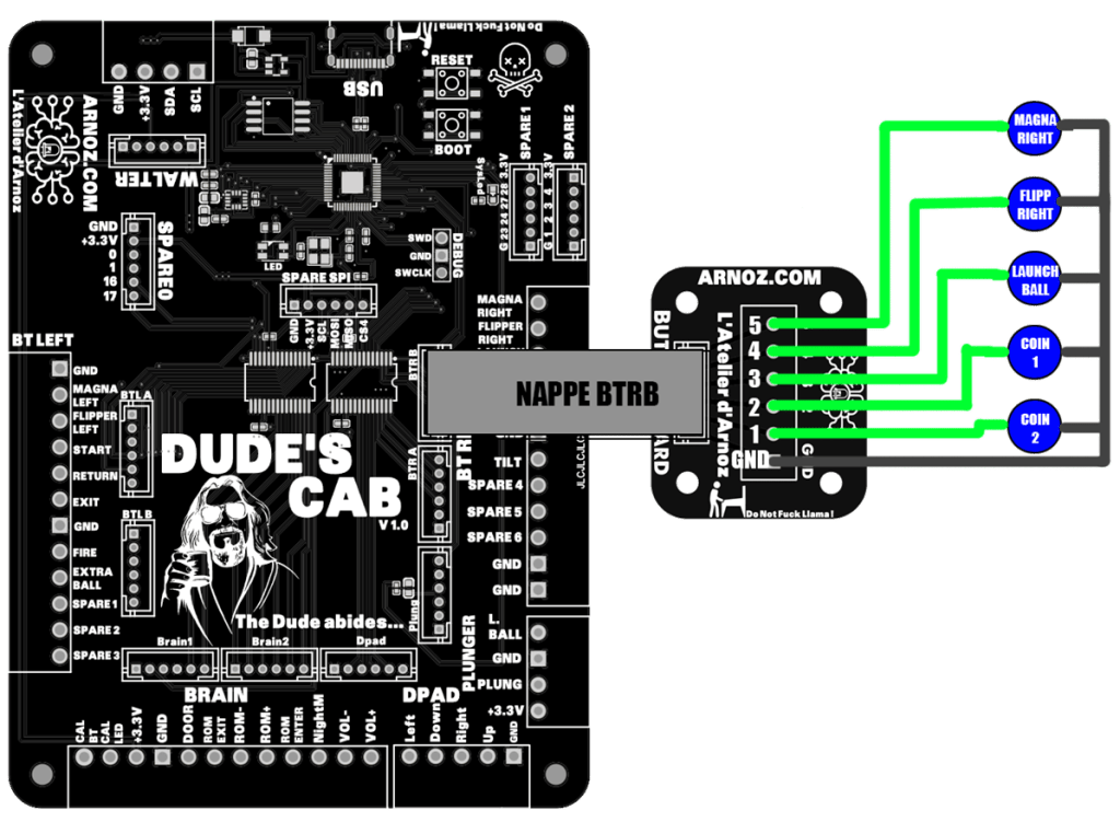
Here is an EXAMPLE of button wiring; adapt it to your needs:
You can use Button Boards to simplify your ribbon cable wiring.
You have 8 sockets for this purpose:
BTLA and BTLB (LEFT A and B buttons)
DPAD (socket for wiring the 4 directions)
BTRA and BTRB (RIGHT A and B buttons)
PLUNG for the Plunger
Refer to the tables and example to fully understand the correspondence with the BUTTON BOARDS.
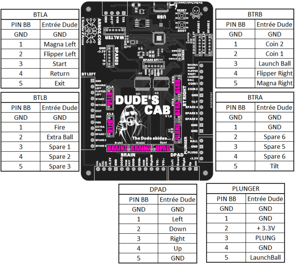
2-PLUNGER WIRING
You can use the 4-pin connector or a ribbon cable to wire your Plunger (based on a 10KOhms linear potentiometer or a POTAR).
A Launch Ball input is available if you have a button at the end of your Plunger (this function can be emulated by the Dude’s Cab, so the button is no longer necessary if you don’t have one).
Connect the corresponding pins via the connector or ribbon cable.
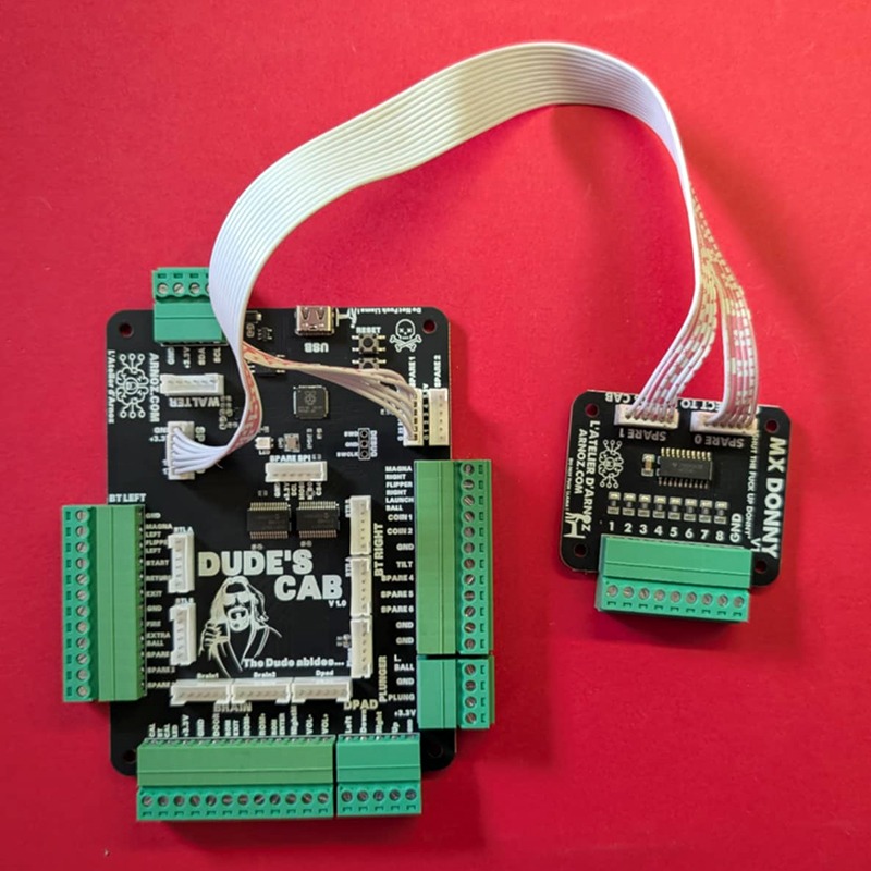
3-WIRING THE MX DONNY
You will use the two 6-pin JST cables provided to connect the SPARE0 and SPARE1 sockets to each other.
4-SPARE PLUGS
There are several additional ports on the board:
A USB-C port to power the board and enable it to communicate with various software programs.
A WALTER port that allows you to add cards to control your various toys. See the WALTER user manual for instructions on how to use it.
SPARE 0, SPARE 1, SPARE 2, SPARE SPI, and DEBUG ports that will allow you to add functions to your board in the future.
Currently, the SPARE0 and SPARE1 ports are used to add the MX DONNY to control addressable LEDs.
5-LEDS
There are two LEDs on the board.
The first is a small blue LED called SYSLED, which lights up when communication is taking place between the Dude’s Cab and the machine controlling it (PC, console, tablet, etc.).
The second is an RGB LED called LED (original, right?). It provides information on the status of the Dude’s Cab.
The LED will be pink during normal card operation.
The color codes can be found at the end of this document.
6-Buttons on the board
The Dude’s Cab has two buttons, RESET and BOOT. These allow you to troubleshoot or reprogram the card in case of problems by switching it to DFU mode.
To activate DFU mode, plug in the board, press and hold RESET, press and hold BOOT, release RESET, and finally release BOOT. Your board will now be in DFU mode and will appear as a hard drive named RPI-RP2.
7-Firmware Update
There are two ways to update the card’s firmware:
Use the Dude’s Cab Configurator:
This function is explained later in the user manual.
Manual update:
Simply switch the card to DFU mode (as explained in the previous chapter) and download the UF2 update file. Once your Dude’s Cab has been switched to DFU mode, a new disk will appear on your workstation. Simply drag the UF2 file onto the hard disk, and you’re done.
IMPORTANT! Updating the firmware does not reset the card’s configuration. Use the configurator for this.
B – Configuration
1-Dude’sCabConfigurator
The software used to configure Dude’s Cab is called Dude’s Cab Configurator.
It is available at this address: https://dude.arnoz.com/DudesCab/DudesCabConfigWinInstaller.msi
Install it like any other software, then launch it.
INSTALL THE SOFTWARE FOR ALL USERS!!!!!
Connect your Dude’s Cab to your PC using the USB-C cable.
You will be taken to the home screen.
By clicking on DIRECT OUTPUT in the bottom right corner, you will have access to the DOF installers. Simply install them and launch RegisterDirectOutputComObject.exe (32-bit version only).
Tooltips will appear when you hover your mouse over the various functions.
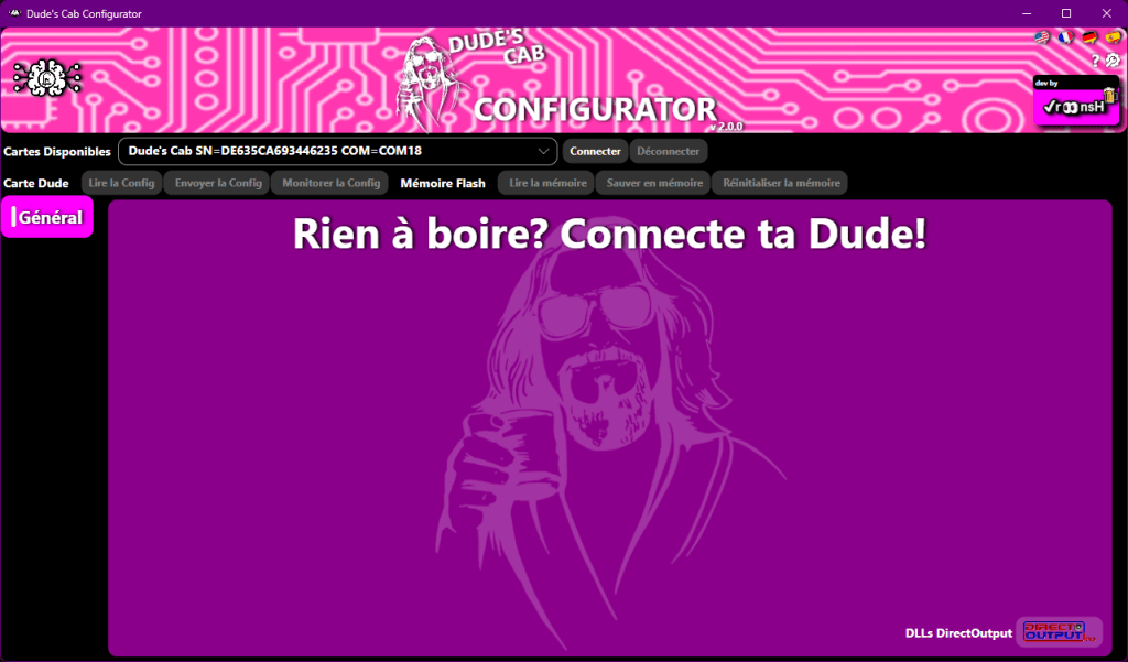
Général
First, select your language using the flags in the top right corner.
In the drop-down menu, you should see your Dude’s Cab with its COM port and serial number.
To connect the configurator to the Dude’s Cab, simply click on the Connect button.
To disconnect, simply click on Disconnect.
Once connected, the various tabs will appear, and you will also be able to see the firmware version of the Dude’s Cab.
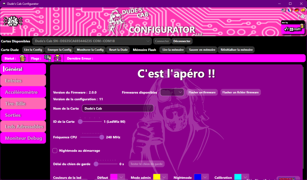
At the top, you have a bar providing you with various information:

Status shows you a beer if the connection is OK.
Flag gives you information such as ADMIN MODE and the current status of NIGHTMODE, and next to it you will see the last error, if any.
Here are the various icons:

Idle : Board is connected

Admin mode

Calibration

Error

Nightmode OFF

Nightmode ON

Shift

Warning
You can now navigate between the different tabs by clicking on them.
From now on, the Configurator and Dude Card Flash Memory buttons are accessible.
They allow you to send and receive configurations between the card and the configurator, and to manage the backup of these configurations.
Dude Board:
- Reading the configuration allows you to retrieve configuration information from the card, if, for example, you have messed around with things without saving them properly, and you want to revert to the configuration on the card to undo all the mistakes you made while under the influence of alcohol.
- Send Config allows you to send the changes you have made in the configurator to the Dude’s Cab. Once you click, the Dude’s Cab will use these new settings to operate.
- Monitoring the configuration allows you to display the configuration in the debug monitor.
- Resetting the Dude simply means disconnecting it and then reconnecting it. Certain settings, such as the CPU frequency, LED chipset, or Watchdog duration, require the Dude to be reset.
Flash memory:
- Reading the memory allows you to restore the settings saved in the Dude’s Cab.
- Saving the memory allows you to store the parameters you have just sent to the Dude’s Cab in its memory.
- Resetting the memory allows you to reset the settings in the Dude’s Cab.
Please note that the Dude Card section does not allow you to save the configuration; it only allows you to send it to the card to test it, or retrieve it from the card. If you reboot the card, this configuration will be lost.
In order for Dude’s Cab to retain the configuration once disconnected, you must click Save to Memory after clicking Send Config.
If there have been changes in the Config Tool that have not been sent to the Dude’s Cab, a small icon will move next to Send Config.
If the configuration sent to the Dude’s Cab has not been saved to the card, a small icon will move next to Save to Memory.
The Flash Memory section is used exclusively to manage the backup of what has already been sent to the card.
Don’t forget to click Send Config so that your changes are taken into account by the Dude’s Cab, and click Save to Memory if you want the Dude’s Cab to keep the changes in memory.
Firmware Version: allows you to see the firmware version on the Dude’s Cab.
Available Firmware: allows you to see the available firmware versions via the drop-down menu.
Flash Firmware: allows you to flash the firmware version selected via the drop-down menu on the Dude’s Cab.
Flash a Firmware File: allows you to flash the selected uf2 format firmware version via the window that will open on the Dude’s Cab.
Card Name allows you to give your Dude’s Cab a name.
Card ID allows you to choose your card number (if you are using more than one) to match the DOF ini file number (default 90).
CPU Frequency allows you to choose the speed of the card’s core. The default is 200, with 240 being the maximum. Increasing this value will increase the speed and performance of the card. If you encounter bugs, decrease this value.
Night Mode on Startup allows you to force the Night Mode setting so that it is enabled by default at boot time.
Watchdog timeout allows you to automatically reboot the card in case of a crash. If the value is set to 0, this function is disabled. You set the time during which the card must be blocked to reboot automatically. The TEST WATCHDOG button allows you to test this function.
LED colors allows you to choose the LED colors for the different modes. Use a bright color because in pulse mode its value is halved.
Load a DUDE file allows you to load a configuration backup from your PC.
Save a DUDE file allows you to save your configuration on your PC.
Open the log file allows you to retrieve the configurator logs.
DirectOutput DLLs opens a window with the Direct Output X32 and X64 installers.
Inputs
Here we will configure the functions of each button input.
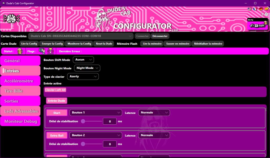
Shift Mode Button The drop-down menu in front of the Shift Mode Button allows you to activate the Shift function of the buttons and configure the Shift key. You will notice that once the key has been configured, the function is activated, and a new drop-down menu appears in front of each button entry named Shifted, allowing you to configure the Shift function of each button (except in front of the button that serves as Shift, of course…).
The Shift function allows you to assign a second function to a button (for example, to manage the sound of different SSF amps, or to display table information, without making the front of the pinball cabinet look like the face of a young teenager with acne…) a bit like the Shift key on a keyboard, which allows you to have two characters on the same key.
I call the button that acts as Shift the Shift function, and I will call the secondary functions of the other buttons Shifted.
Simply press the Shift button and, while holding it down, press another button to activate its Shifted function.
Avoid giving the Shift function to the Flipper, Magna, or Fire buttons. This is because the Shift button sends its action when the button is released (because as long as it is pressed, it waits to see if another button is used, and if another button is used, it will no longer perform its primary function and will just serve as Shift), which would make it unplayable.
Night Mode button The second drop-down menu allows you to change the input that activates or deactivates Night Mode. Select the input using the drop-down menu.
Keyboard Type allows you to choose your keyboard type so that the shortcut keys match. Select the keyboard that corresponds to yours.
Active Input allows you to view keystrokes in real time by showing you the activated keyboard key or joystick button.
Stabilization Delay allows you to correct the multiple keystroke bug. In the event of multiple keystrokes, increase the value slightly until you find the one that no longer causes the bug.
Input configuration
Each line corresponds to a physical input on the Dude’s Cab.
There are two types of inputs at the hardware level of the card:
- Five inputs that are connected directly to the card’s controller to optimize input lag (the reaction time between when the button is pressed and when the computer receives the information). These are the Flipper Left & Right, Magna Left & Right, and Fire inputs. Use these inputs for these functions as a priority.
The other inputs go through a multiplexer and have slightly higher latency.
The name in the pink square corresponds to the name of the input on the card. This is a suggested function; you can of course use the input as you see fit (for example, use the Extra Ball input to connect a Coin button; you just need to assign the correct function to this button in your software).
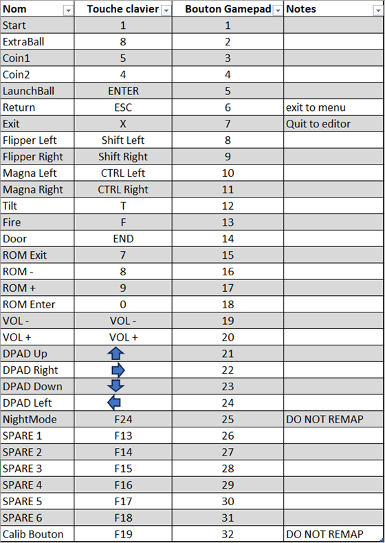
You can assign either a joystick button or a keyboard key to an input using the drop-down menu. Inputs Button 1 to 32 correspond to the 32 buttons on the joystick, and the Keyboards inputs correspond to the keyboard keys.
If you use the Shift function, you can assign the Shifted function (which will be activated when the shift button is pressed at the same time as the key) in the same way.
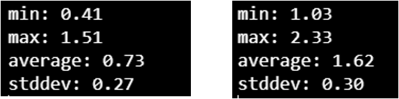
Finally, you have latency control with two options: Normal and Optimal, to further adjust the input lag.
I mentioned earlier that we already had five optimized inputs, but we wanted to optimize this even further by creating an ultra-fast, priority Optimal calculation loop, which we chose to put on the Flipper, Magna, and Fire inputs. We think it’s best to leave only these inputs in order to optimize calculation time, but we’ll give you the keys to change this and configure everything to your liking.
The second Normal loop is for all the other buttons that don’t necessarily need crazy latency. PLEASE NOTE, you have the figures, the Normal latency is still excellent!
The tests were carried out using the method available here: https://inputlag.science/controller/methodology
Current Burn latencies: LOW: 0.73ms Normal: 1.62msi : https://inputlag.science/controller/methodology
Latences Burn actuelles : LOW : 0.73ms Normal : 1.62ms
Accelerometer
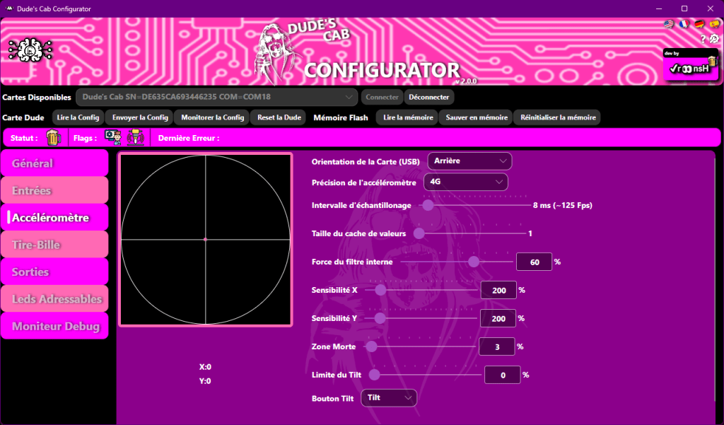
This section allows you to manage the card’s accelerometer functions, which you will use for Nudge (table jamming!).
At any time, you can see your accelerometer live in the middle of the cross, represented by this beautiful little pink dot. Below, you will see the X and Y positions of the Nudge in real time.
Card Orientation allows you to adjust the orientation of the card by specifying the location of the card’s USB port. If the port is at the back of the Pincab, choose Back; if it is on the right, choose Right; if it is on the left, choose Left; and if the port faces the player, choose Front.
Accelerometer Accuracy allows you to change the range of the hardware accelerometer (greater => loss of accuracy).
Polling Interval Interval at which nudge information is sent. You should set it to approximately the game frequency, no need for more (it can impact input latency).
Value cache size Smoothing cache for hardware accelerometer values, useful for canceling out interference from toys.
Larger => more smoothing, but loss of precision and increased latency.
When set to 1, an internal filter will be applied by the firmware, which is sufficient to adjust for certain types of interference or when there is no interference.
Internal filter strength Internal filter strength, use of the previous value (0% -> only the new value).
X and Y Sensitivity allows you to change the sensitivity of the Nudge to best suit your configuration. The default value is 200.
Dead Zone allows you to adjust the dead zone of the Nudge in which it will not activate. When you change this value, you will see it appear as a green circle in the visualizer.
Tilt Limit allows you to manage the virtual Tilt zone. You can see it appear visually as a red circle in the visualizer. If the accelerometer enters the zone, it presses the Tilt button.
Tilt Button allows you to choose which button is assigned to the Tilt function.
A few tips for adjusting the nudge:
Check with the basic settings to see if any toys activate the nudge (preferably in-game to see how the ball behaves).
If there are any, to smooth the signal:
- Method 1: increase the strength of the internal filter.
- Method 2: increase the size of the read cache (the larger it is, the more latency and loss of precision you will have).
If it still nudges: - Increase the range of the accelerometer. (will lose precision)
- Try putting a dead zone in the center to get rid of small interferences
Still nudging? Check that your Dude is properly isolated from vibrations in your cab.
When there are no more interferences, increase the sensitivity until it’s perfect!
PLUNGER
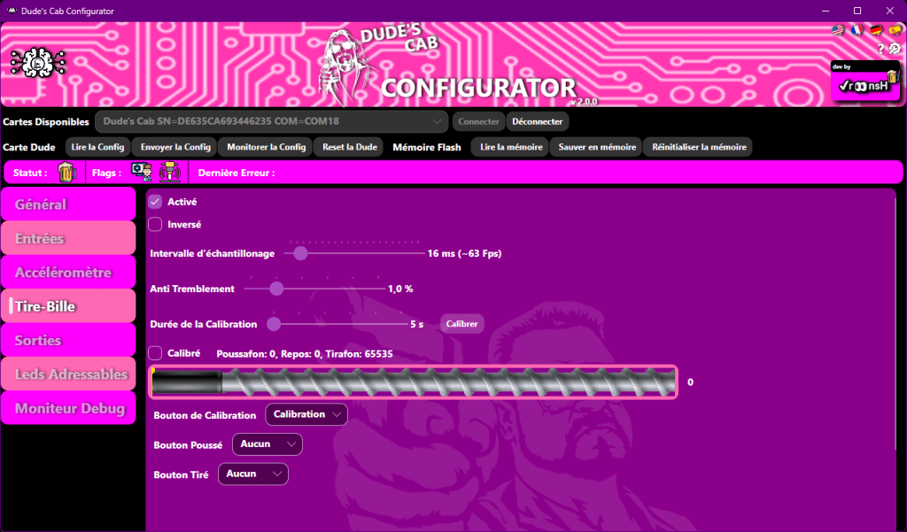
This section is relevant if you have a real plunger on your machine, as it allows you to configure it. If you don’t have one, simply uncheck the Enabled box.
Enabled allows you to activate the plunger by checking the box.
Inverted allows you to reverse the direction of the potentiometer if it is not going in the right direction.
Polling Interval allows you to set the frequency at which the card will check the position of the Plunger. Leave it at 16ms by default.
Anti-Shake allows you to set a dead zone to prevent the Plunger from shaking.
Calibration Duration allows you to set the duration of the Plunger calibration. The Calibrate button allows you to start the calibration.
Calibrated is checked if the plunger has been calibrated.
Calibration Button allows you to choose the button that starts calibration.
Pushed Button allows you to choose the virtual button function when you push the plunger.
Pulled Button allows you to choose the virtual button function when you pull the plunger.
PLUNGER CALIBRATION
To calibrate the plunger, start the calibration process, then move the plunger fully in both directions.
OUTPUTS
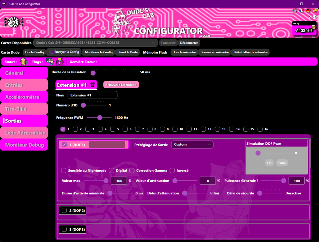
This section allows us to configure Walter expansion cards and their small MOS.
To add a card, simply click on New Extension and confirm by clicking Yes.
To delete a card, simply right-click on its tab and select Delete.
You can name this card in the Name field to help you identify it. This is for your own reference, so you can use any name you like.
You can then set the card’s address using the ID Number slider, which must correspond to the address you set on the card using the dip switches.
PWM Frequency allows you to change the frequency of the card’s PWM outputs if your toys make a whistling sound when activated (often the coils).
You will then find 16 boxes corresponding to the 16 outputs on the card, each with its own specific options.
Check the box next to the output number to activate the output.
The number in the pink square indicates the output number. You can write the name you want to give to this output next to it to simplify configuration.
The number next to DOF corresponds to the corresponding output number in the DOF. It changes depending on the card address.
Sensitive to Night Mode is a checkbox for noisy toys. If the box is checked, the toy will not activate when Night Mode is activated.
Digital allows you to use the output as a digital output, i.e. ON or OFF, without dimming.
Gamma Correction allows you to assign a specific curve for RGB light toys. If this is the case, check this box.
Inverted allows you to invert the output logic (if the box is checked, the output does the opposite of what is requested; it turns on when turned off, and vice versa).
Max Value allows you to choose the maximum voltage that will be applied to the output on a scale of 0 to 255. For example, if you set this parameter to 127, the toy will receive half the voltage; at 63, it will receive only a quarter…
The next two options allow you to set up Chime Logic and Flipper Logic. Chime Logic allows you to cut the voltage to the toys after a given time, which is useful, for example, for Knocker coils, to prevent them from overheating. Flipper Logic reduces the voltage of a toy after a given time, as in the case of real pinball flippers used in toys. You apply the call voltage to activate the toy, then reduce this same voltage after a few milliseconds to hold the coil in place, but reduce the voltage to prevent the coil from overheating.
Attenuation Value allows you to set the voltage applied after a certain amount of time. If this value is zero, it activates Chime Logic (because the voltage will be zero after X ms); if the value is greater than zero, you will activate Flipper Logic.
Attenuation Delay allows you to select the time after which the toy will have the FallOff Value voltage in ms.
Minimum Activity Duration allows you to set a minimum activation time for the output (each time it is activated, the output will be activated for at least this time, even if the command is cut).
General Power! allows you to set a general output level for the output, which then modifies the Max Value and FallOff Value proportionally.
The TEST functions allow you to test the outputs, taking into account settings such as Chime or Flipper Logic, as well as the Max Value and Night Mode.
The Pwm Values slider allows you to test with a variable voltage by sliding the slider from 0 to 255. The ON button allows you to test the output at 100% of its configuration by clicking on it, which then switches to OFF. The Pulse button allows you to send a pulse with a duration corresponding to the value set on the top Pulse Duration slider.
You also have a choice of presets for each output with the Output Preset drop-down menu.
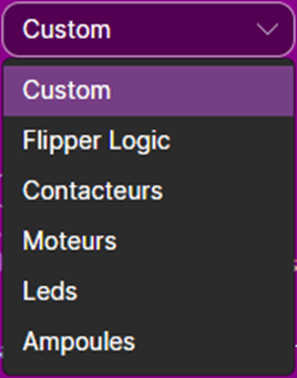
Custom gives you access to all settings.
Flipper Logic allows you to activate the corresponding sliders.
Contactors allows you to activate Chime Logic and switch the output to Digital (ON and OFF only).
Motors allows you to activate the corresponding sliders.
LEDs allows you to activate the corresponding sliders and activate Gamma Correct.
Bulbs allows you to activate the corresponding sliders.
Safety delay allows you to assign a safety delay for the output, which will cut the output after the selected time.
ADRESSABLE LEDS
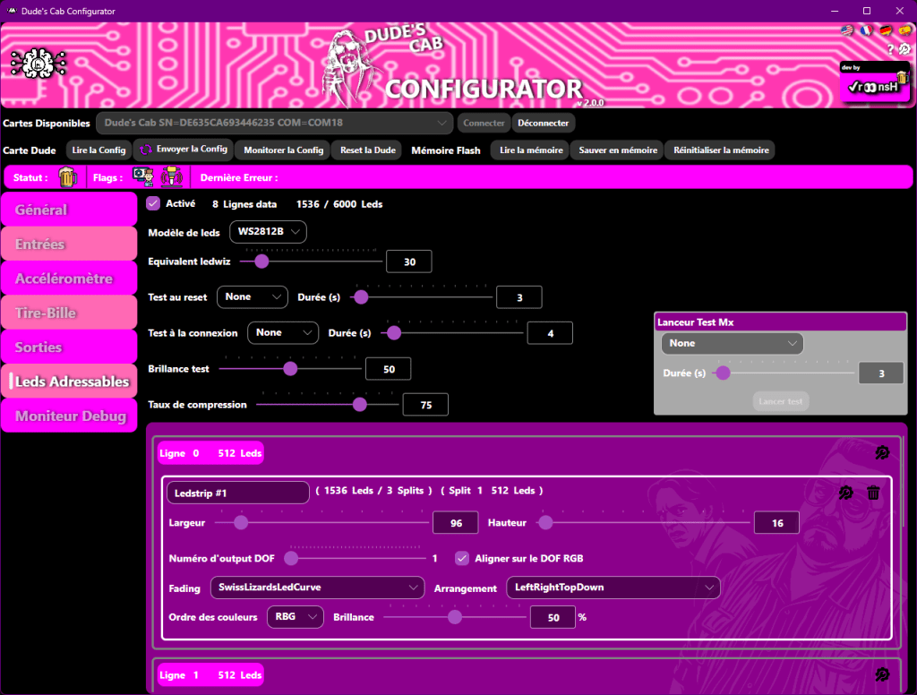
Enabled allows you to enable addressable LED management if you have an MX DONNY. On the right, you will see the number of LEDs in your configuration.
LED model allows you to choose the type of LEDs in your configuration, usually WS2812b.
LEDwiz equivalent Sets the same LEDwiz equivalent number as on the dofconfigtool website.
You must have entered a WS2811 device, so it will be 30.
Test on reset This test will be triggered when the Dude turns on or after a reset. RGB is a red, green, blue test, Colors is a test that cycles through several colors, and Laser is a running light that helps you find the wiring direction of the LEDs. The duration of the test can be set on the right.
Test on Connection This test will be triggered each time there is an external connection request (Directoutput, Pinup, etc.).
This will help you verify that the Dof is properly connected to your card.
Brightness test: here you can adjust the brightness of the test.
MX test launcher: allows you to launch the test selected from the configurator.
Compression rate: MX data will be sent without compression if the compression ratio is higher than this setting (0 never compressed, 100 always compressed).
You have 8 outputs from 1 to 8, which correspond to the 8 physical outputs of the MX DONNY. Each output can control 512 LEDs (to maintain smooth animations), and each output can control several different functions. For example, you can mix sides and MX buttons on a single output.
To add a LED strip, click on the icon on the right.

and select ADD LEDSTRIP
You will see this window
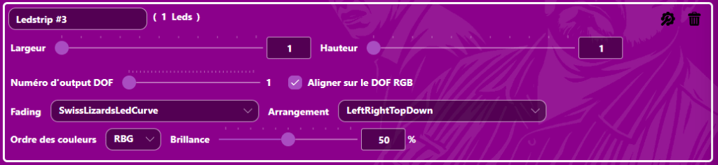
Fill in the various information requested:
Give your LED strip a name for clarity.
Width/Length Here you will set the total dimensions of your LED strip (including splits).
This is the main description of the LED strip that will be used by the DOF to play the effects correctly.
DOF output number This must correspond to the first DOF number in the RGB field of your LED strip on the dofconfigtool website.
Align with DOF RGB This will automatically jump by 3 to match the usual numbers on the dofconfigtool website.
Fading Choose a fade curve:
– Linear: no remap
– Linear0to224 -> Linear0to16: this linearly remaps 0->255 to 0->x, basically a brightness remap (we now have a separate brightness setting).
– InvertedLinear: 0->255 will remap to 255->0
– SwissLizardLedCurve: remaps with gamma correction (best choice)
Arrangement Select the LED arrangement that corresponds to the installed LED strip.
Color order If you have set the LEDChipset correctly, the Dude will internally manage the color order specific to each model.
Normally, you should leave RGB here.
Brightness Max brightness of the strip.
SPLIT One output can drive a maximum of 512 LEDs to remain fluid. If, for example, you are using an HD backboard consisting of 6 panels of 16X16, you will need to use the Split function because you will end up with 1536 LEDs, and therefore connect 2 panels per output, using consecutive outputs. To configure this, enter a LED strip in the first line that will be the total size of your backboard, i.e., in our example, 96 wide and 16 high.
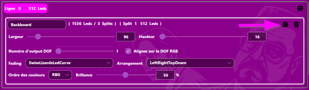
Then click on the icon on the right and select Add a split
This will open a box in the next line with the same name as the one you just configured, with a new slider.
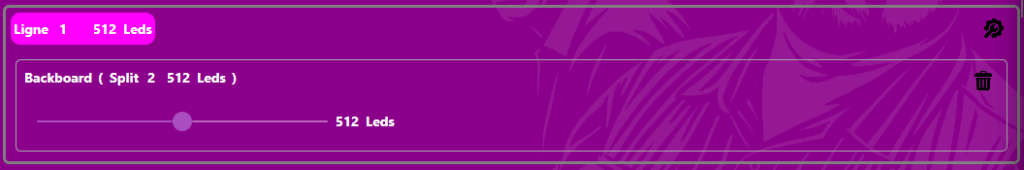
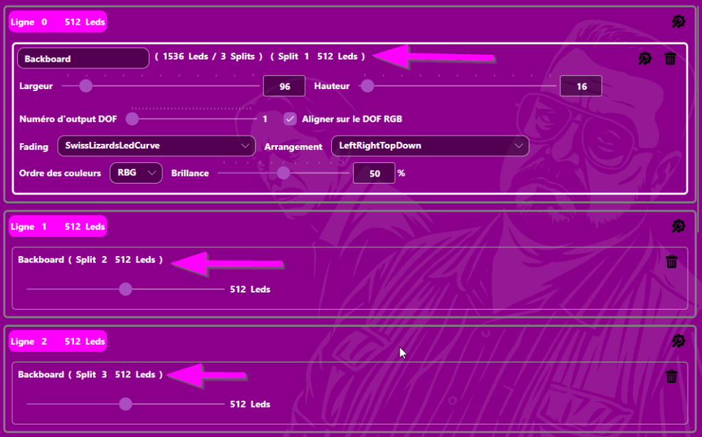
Here you will choose the number of LEDs on your second output (in our example, 512)
and you will repeat this for the third output.
You will therefore end up with three splits of 512 LEDs, which corresponds to our example with a total of 1,536 LEDs for the split.
DEBUG MONITOR
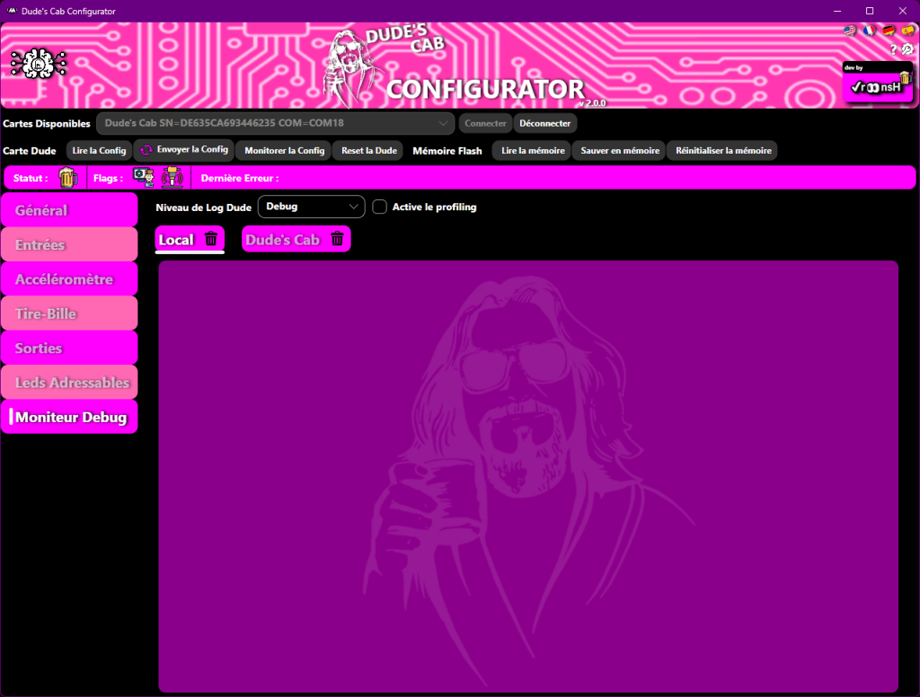
This part of the configurator will help you troubleshoot any configuration or hardware issues.
Local Displays the configurator-side logs.
Dude’s Cab Displays the configurator-side logs.
The Dude Log Level drop-down menu allows you to choose the level of logs displayed.
None No logs.
Errors Only errors are displayed.
Warnings Only warnings are displayed.
Info Only information is displayed.
Debug Everything is displayed.
LED CODE
Here is the meaning of the different signals that the RGB LED on the Dude’s Cab can send you:
ON: Steady light that does not change state
HEARTBEAT: LED lit with a double flash (beating heart)
SINE: LED changing from one color to another with a smooth effect
SWITCH: LED flashing from one color to another in a sharp manner
Default colors (if you change them, this will change )
- Pink/Pink HeartBeat: The Dude’s Cab is operating normally.
- Pink/Yellow HeartBeat: The Dude’s Cab is connected to the configurator (Admin Mode).
- Blue/Pink SINE: The Dude’s Cab is in NightMode.
- Blue/Yellow SINE: The Dude’s Cab is in NightMode and connected to the configurator (Admin Mode).
- Cyan/Black SWITCH fast: Plunger calibration in progress.
- Orange/Black SWITCH: WARNING depending on the number of LED flashes.
- Red/Black SWITCH: ERROR depending on the number of LED flashes.
ERROR CODE:
If the Dude’s Cab is faulty, it will send an error code by flashing the RGB LED in orange or red. The number of flashes indicates the type of error:
- 1 « Init CPU Frequency »
- 2 « Init Inputs Multiplex »
- 3 « Init Admin device »
- 4 « Init Pwm outputs device »
- 5 « Init ALed outputs device »
- 6 « Init Walter drivers »
- 7 « Init Keyboard device »
- 8 « Init Gamepad device »
- 9 « Init Accelerometer »
- 10 « Init Plunger »
- 11 « Flash memory save »
- 12 « Flash memory load »
- 13 « Send config to Admin »
- 14 « Incoming communication overflow »
- 15 « Incoming command ignored »
- 16 « Plunger calibration »
- 17 « PWM Output on non configured Walter »
- 18 « PWM Output on disabled Walter output »
- 19 « PWM Output security reset »
- 20 « Comm buffer invalid size »
- 21 « Comm buffer write overflow »
- 22 « Comm buffer missing data »
- 23 « Comm buffer invalid seek »
- 24 « Watchdog causes DudesCab reboot »
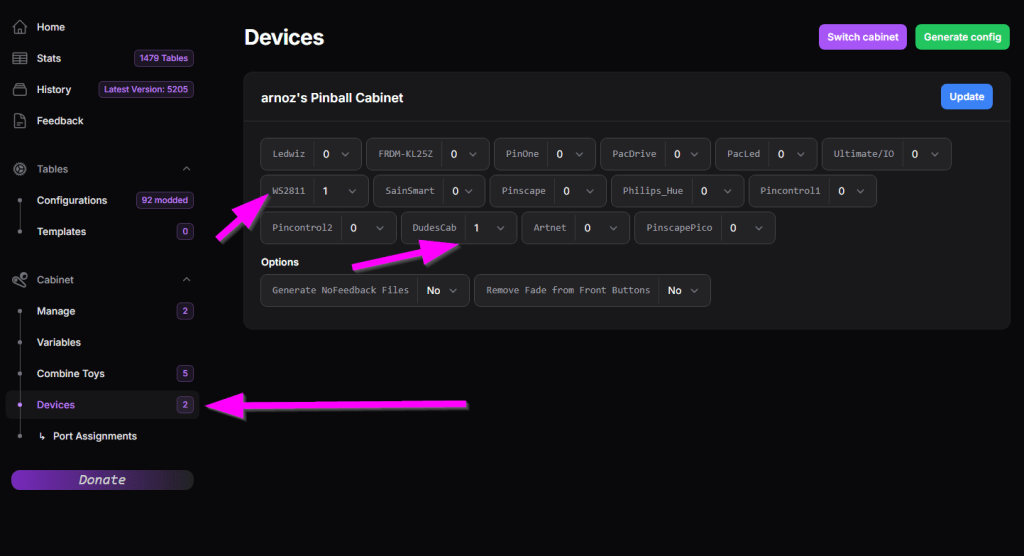
DIRECT OUTPUT FRAMEWORK
To configure the outputs of your Dude’s Cab in the DOF, enter 1 in front of Number of DudesCab Devices in the Devices tab, and if you have an MX DONNY, enter 1 in front of WS2811, then save.
Then click on the Port Assignments tab and select DudesCab 1 directoutputconfigini90 in Device to configure your classic toys.
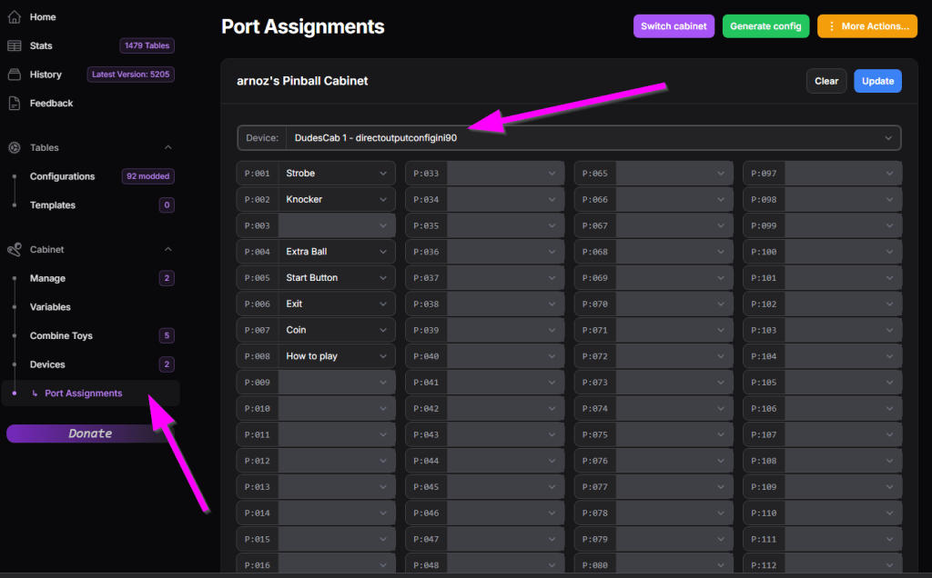
Then configure each output port to match your configuration in the Dude’s Config Tool.
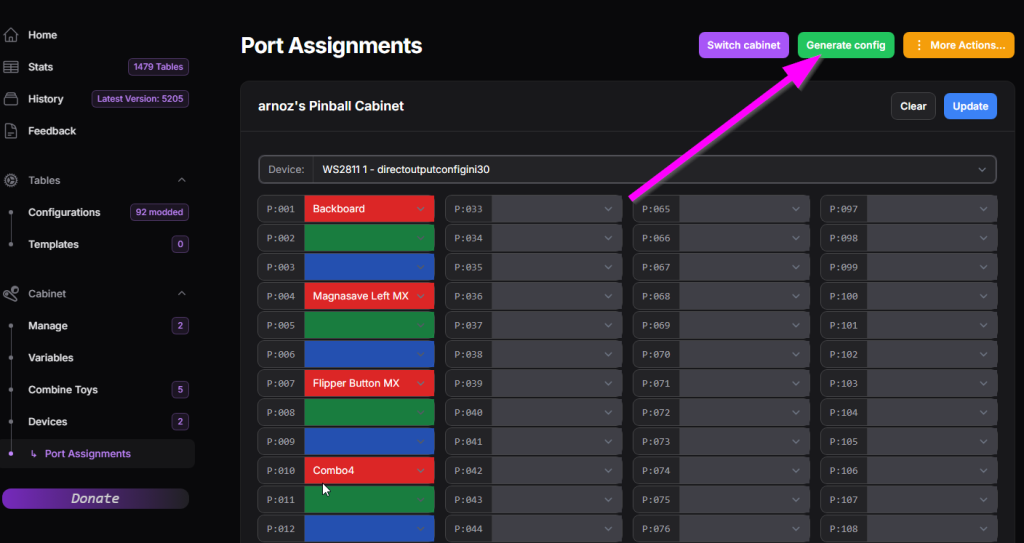
If you are using an MX DONNY, click on Device to access the WS2811 – directoutputconfigini30 page to configure your LEDs.
WARNING!!! With MX DONNY, you must not have a cabinet.xml file.
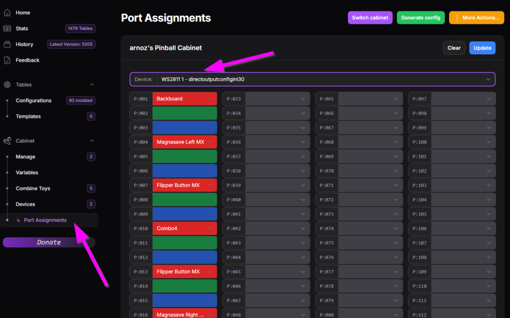
In front of each output, enter the function of each LED strip, using the numbering you entered in DOF output number on the configurator.
Save.
Download the configuration by clicking on Generate config.
Unzip and unlock the files, then place them in your Direct Output config directory.
Be sure to place the new DLLs in the configurator as indicated at the beginning of the manual.
UPDATE :
Configurator 2 :
- New addressable LEDs tab,
- Dude status displayed in config,
- Firmware 1.1.2 backward compatibility with adaptive interface,
- stranger tooltips,
- settings,
- ability to enter slider values using the keyboard,
- nihilist validation,
- new firmware flash via combo or manual with device reinstallation,
- dude reset from config,
- right Alt supported in keyboard keys
Firmware 2 :
- Well, MX support, obviously.
- Per input debounce delay,
- Per extension PWM frequency,
- Adjustable CPU overclock,
- New accelerometer filters,
- Safety delay per output,
- Adjustable activity LED colors.
- Watchdog
Configurator 1.1.5 :
– fix the update button when nightmode button is changed
– ignore dudecard answers for other tools (DirectOutputConfigTester for instance) when configurator is connected
– new upgrade directories support
Firmware 1.1.2 :
– Doflinx support (tks to DDH69 ![]() ) !!
) !!
– new Dof handshake & informations
– low pass filter on accelerometer outputs
– snap on plunger still if last read is inside the jitter window several Dof fixes (alloff command support, init, nightmode with falloff outputs…)
– logs are not sent when admin is not connected
– fix coin1/coin2 inputs inversion
DirectOutput DLLs :
– All modifications are now integrated into latest Mjr Beta releases new switchable DudeCab instrumentation when you need Dof debug
(use <Instrumentation>Dudescab</Instrumentation> in your GlobalConfig)
– force AllOff command when all outputs are at 0
– new DudesCab handshake & protocol (only updates up to the latest configured output)- All modifications are now integrated into latest Mjr Beta releases new switchable DudeCab instrumentation when you need Dof debug
(use <Instrumentation>Dudescab</Instrumentation> in your GlobalConfig)
– force AllOff command when all outputs are at 0
– new DudesCab handshake & protocol (only updates up to the latest configured output)
Configurator 1.1.2 :
– Fixed bug causing inputs to be overwritten when removing an Outputs extension (clear button instead of the old right-click menu)
– Update notification sent to Dude when changing the name of an input
– No more update searches if you are not up to date on the Configurator
– Update report window
– New Clear button on the monitoring tabs
– New Outputs window with a checklist of all outputs for an extension, available at all times
Firmware 1.1.1 :
– Better debug info and error codes displayed in the log.
– Fixed names at maximum capacity that were not saved (Dude, Name, Extension name, output name).
– Fixed DOF bugs (clear mal treated, DOF command multi outputs on several extensions simultaneously).
– Fixed bug causing the card to freeze on certain configuration sends from the configurator
– Support for receiving commands (admin or DOF) while a command is being processed by the Dude (previously ignored -> problem with lost DOF commands)
– No more virtual button (LaunchBall) assigned by default to the push of the bill pull